


Setup Guide
GT-MAX32
Meet the GT-MAX32, designed with unwavering dedication for the no-compromises competitive sim racer. It encapsulates the spirit of a GT racecar while delivering exceptional performance, comfort, and durability.
Contents
Downloads
- Applications
- SimHub Files
Wheel Layout
Get familiar with your GT-MAX32.

GT-MAX32
Front
- 15-inch Touchscreen Display
- 2Hand Laid Carbon Fiber
- 3RGB Telemetry Strip (4+16+4)
- 47-Way Switches (x3)
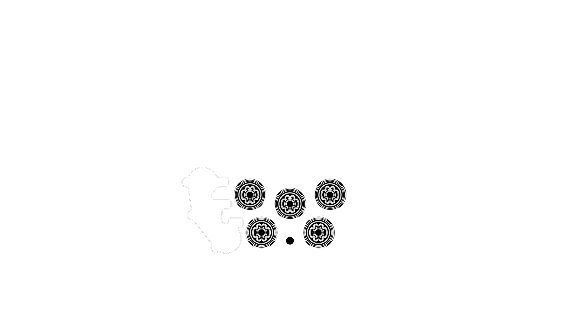
- 5RGB 5-Way Encoders (x5)
- 6RGB Buttons (x8)
- 7Silicone Handles

GT-MAX32
Rear
- 8N52 Magnetic Shifters (x2)
-
970mm Bolt Pattern (PCD)
Optional AH50 Pictured -
10HSE Clutches (x2)
Optional Upgrade Pictured - 11GSI USB Cable Connector
Mounting to Wheel Base
The first step in setting up your GSI wheel is to mount it properly to your wheel base.
MOUNTING WARNINGS
GSI wheels are designed for broad compatibility with most hubs and quick releases on the market via the 70mm bolt pattern (PCD). For safe and proper installation, please follow these guidelines:
-
Prefer Using Non-Threaded Mounting Accessories
Attach hubs or quick releases using non-threaded holes to avoid potential damage.
-
Use Captive Screws for Threaded Mounting Accessories
If your hub or quick release requires mounting with its own threads, use Captive Screws to safely connect them. Never use regular screws for thread-to-thread connections, otherwise you will damage the mounting accessory and wheel.
-
Avoid Long Screws
Before connecting a hub or quick release, ensure the screws won't extend more than 4mm into the wheel body once attached, as this may damage internal electronics.
-
Provide USB Cable Clearance
Maintain at least 50mm of space between the wheel body and wheel base to prevent the coiled USB cable from making contact with the base.
Mounting Install Guides

QRS-1
Read

AH50 / AH100 Hub
Read

SC2-X
Read
PC Setup
Once your wheel is mounted, follow the steps below.
USB CONNECTION NOTICE
Using a
power-injected USB hub
helps prevent connectivity issues.
We highly recommend using the following connection method:

Connect to PC
-
1GSI Coiled USB Cable (PC-Side)
Ensure your powered USB hub is connected to your PC and power source, then connect the cable to the powered USB hub. -
2GSI Coiled USB Cable (Wheel-Side)
Connect the cable to your wheel, ensuring the keyed portion lines up with the connector in the wheel (see Step 3). -
3Keyed Connector
The wheel-side of the cable has a small notch. Ensure this notch is oriented at the top so it easily connects to the wheel. Thread the metal coupling to the wheel until snug.
Upon connection, the wheel will run a startup LED animation. This indicates that your wheel is receiving power and ready to receive telemetry data from SimHub.
Download and install simOS, then follow the steps below.

Start simOS
Open simOS and follow these steps:
- 1Go to All Devices
- 2Click GT-MAX32

Update Firmware
- 3Click Check for Updates
- 4If available, select Update
The GSI simOS app automatically installs SimHub for you.
If you need to install SimHub manually, download it below.


Add Device
Open SimHub and follow these steps:
- 1Go to Devices
- 2Click Add device

Select GT-MAX32
- 3Select GSI GT-MAX32
- 4Click Ok

Select LED Colorway
- 5Go to the LEDs tab.
- 6Click the Individual LEDs dropdown and select your favorite.
Note: In the latest version of SimHub, telemetry and button LED profiles are now separate
and managed as individual profiles. This is a change from older versions, where
they were combined.
If you’re experiencing issues, make sure you’re running the latest version of SimHub. Then, delete
your device from
SimHub and restart the setup process from step 1.
Software & Settings
Get more in-depth with the functions of your wheel.
Quick Access Settings
Change settings without needing to leave the simulator.
Config Overlay Dash
Displays and adjusts the active clutch mode and clutch bitepoint.
- 1 Push+Hold the top left and right 5-Way Encoders to enter the Config Overlay Dash.
- 2 Press Up on any 7-Way Switch to change Clutch Modes.
- 3 Rotate the top three 5-Way encoders left or right to adjust the bitepoint value.
- 4 Press any push button to exit the Config Overlay Dash.
Tip: Each 5-Way encoder changes the bitepoint value in different increments:
simOS App Overview
Get detailed information about the way simOS interacts with your wheel. All device settings are stored on-device, so no reconfiguration is required when using the wheel on another PC.
Clutch Modes
Read
Encoder Settings
Read
Other Settings
Read
Cleaning & Maintenance
Pro tips and tricks directly from the GSI production team.
Wheel
Cleaning
Read
Shifter
Maintenance
Read
Clutch
Maintenance
Read
Troubleshooting
For proper operation, you need to have a clean, reliable USB data throughput signal and the absence of EMI (Electro Magnetic Interference) from other devices.
- Connect wheel via a powered USB hub or directly to computer.
- Avoid excessively long USB extension cables. Data degrades on longer USB extensions.
- AMD systems with widely known poor USB performance update to AGESA bios 1.2.0.2 or higher. (check your motherboard manufacturer website)
- Check for EMI (Electro Magnetic Interference) and ground rig if needed.
- Try alternate USB ports if one port is not performing to spec.
- Check coiled cable to make sure cable housing is screwed on tight.
- USB shares data throughput with all devices on the system. Make sure you are not overloading the USB tree.
- Use a dedicated PCIE USB card. (We recommend NEC chipset cards)
We're here to help
GSI SUPPORT CENTER
Every GSI product is made with loving care and craftsmanship.
Providing excellent
customer service is always paramount.
Safe Usage & Warranty
For more information, read the full Terms & Conditions.
Warnings & instructions for safe usage
- WARNING: CHOKING HAZARD - Small parts, adult supervision required! Never let children use the GSI steering wheel, or any of the provided parts or tools without supervision by an adult.
- Never use damaged or in any way defective product, stop using it and contact the reseller or the manufacturer.
- Use protective gloves when changing or adding parts to the steering wheel, or when removing parts from it.
- Always make sure everyone using the GSI steering wheel have read and understood the content of the manual above.
- Always check that all connections and quick releases are tightened before using the steering wheel.
- DO NOT open the steering wheel.
- The GSI steering wheel or any of its parts may not be used for any other purpose than what they were designed for. GSI products are meant to be used as an USB-input device on a computer. DO NOT USE IN A REAL CAR! The manufacturer is not liable for any damage that may result from using the product in violation of the instructions.
- Always fasten the GSI steering wheel to the direct drive base with M5 bolts (6 pcs). It is the user's responsibility to ensure that the platform can withstand the use of the GSI steering wheel.
Operating environment and safe storage conditions
- 15°C – 35°C temperature, non-condensing humidity.
- Do not expose the GSI steering wheel or any provided parts to direct sunlight or moisture.
- Indoor use and storing only.
Warranty
The product has a 1-year warranty, excluding situations and events where:
- Instructions for use or care have been disregarded.
- The product has been used incorrectly or carelessly.
- An accident or other event has occurred after the product has been handed over, in which the product has been damaged by external factors.
- Normal wear and tear in use.
CE-Marking
Product meets EU standards for health, safety, and environmental protection.
Manufacturer: Gomez Sim Industries LLC
Manufacturer address: 1167
Mississippi Ave #100, Dallas, Texas 75207


